S2 Spa Soother - Build the Box Part 1
You'll need access to a laser cutter or send out to a fab service. I used an Epilog 60W Laser and a Universal Laser Systems model at TechShop San Francisco. The settings I used for the Epilog were:
For 1/8"/3mm Revell Brand Birch Plywood
Vector: S=20, P=80, F=500
Raster: S=95, P=90
The different parts of the box are all named in the CorelDraw document: Top Shim, Buttons, etc. There are six sides to the box:
- Top, with buttons
- Bottom, same size as top
- Two vertical sides
- Front, with opening for diffuser and on-off momentary switch
- Back, with opening for speaker and screw holes
So, why the shims? The buttons have a little bit of slop, sideways rotation, when glued onto the switch activator. The shims help reduce that. The buttons fit into the top-plus-shim so sideways motion is restricted.
Breadboard Spacing:
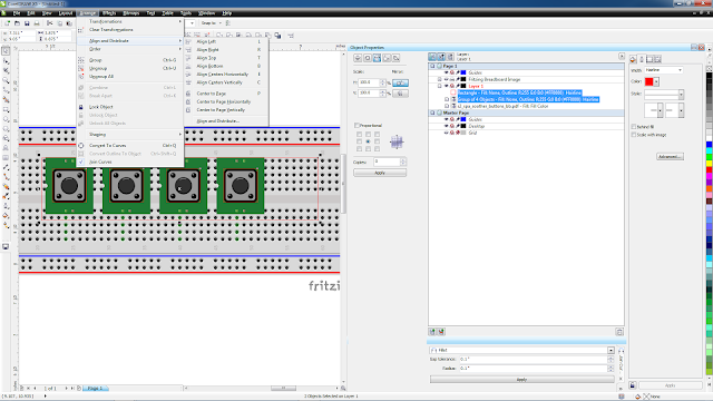
We're going to be soldering our sound buttons to a piece of perma-proto breadboard in a later step, to make the final assembly easier. Fritzing diagram I used is HERE.To get proper alignment of the buttons to the 0.1in/2.54mm pitch of the breadboard:
- make a quick layout in Fritzing of your 12mm momentary switches at the spacing you'd like
- Export the Fritzing layout as a PDF document
- Import the PDF into CorelDraw/AI/Inkscape
- Adjust and repeat as needed
- To Center your switches in another object in CorelDraw, like the box top in this case:
- Group the switches
- Select the box top outline, then shift-click the Group of switches
- TIP: All selected objects will align to the last selected object. In this case the switches will move relative to the box top
- Arrange/Align and Distribute/Align Objects Vertically (or Horizontally depending on your situation)
Aligning Button Outlines to Breadboard Spacing in CorelDraw
Already included in the CorelDraw document are custom raised letter button tops. You can use these or the stock plastic tops. If you don't want custom buttons, skip down to Prepare the Lens.
Using CorelDraw, create your text with the Artistic Text tool as normal, sized to fit in a round or square button. Use Convert to Curve on the text.
In the screenshot below, the text ("Ocean") has been converted to NoFill inside a square-shaped button object. Because it's NoFill, you can't see it in the screenshot.
Next, select the surrounding object and use Uniform Fill/Black, as shown in the following screenshot.
When you send these objects to an Epilog laser (from CorelDraw) with proper raster settings, the black area surrounding the text will be etched, leaving the text slightly raised above the background.
To attach the custom buttons to the momentary switch:
- glue the top (raised letter portion) to a base (hole cut in center); allow to set overnight
- DON'T GLUE the button to the momentary switch yet! We'll do that in a later step, Wire Up the Circuit and Test
Glue the shim to the inside of the top/button cutout. You can use the buttons themselves to hold the shim in place while the glue sets. Just be careful not to get any glue onto the buttons themselves, at this point.
In a later step, we will be soldering the buttons to a cut-down piece of perma-prototyping board (from Adafruit) to make assembly easier.
You'll want to glue some interior components before assembling the box.
Prepare the Lens
With the scored side up, place the scored line over the edge of a table or other sharp surface. Place the straight edge right next to the scored line and press down firmly on the straight edge to hold it in place. Finally, quickly snap down. With luck, you'll have a nice clean edge:
Finish up by repeating the process in the other dimension for the lens.
Now, glue the lens to the inside front opening of the box, smooth side of the material facing out.
The CA glue I was using allows extra time to position your glued piece. However, it still sets up fairly quickly.
Using TiteBond II or similar wood glue, glue the two ascending sides, bottom and front of the box. Put the top (button cutout) in place but DO NOT GLUE the top in place yet! Use a clamp to hold the sides tight. I applied the glue to one side of the finger joints with a cotton swap ("Q-Tip"), finishing with a line of glue on the inside. Better still would be a fine brush, but the swabs were all I had available. If you get glue where it doesn't belong, clean up with a damp cloth.
OK, let's stop here and let that set for awhile. We will come back to the box in Final Assembly.
Get Some Sounds, Next


Comments
Post a Comment