MiniZ: Tiny Streaming Radio Based on Classic Zenith "Cube"
This post originally appeared in a different, shorter form on hackster.io. TL;DR: go to the hackster post.
The Maker’s Journey
On hackster, you get a little bit of “why” with a lot of “how” - a focus on building. Here we’ll see more “why” things turned out the way they did: the thinking, experimentation, and design goals of the project. Call this “The Maker’s Journey”, a peek inside the Maker’s mind.
I had wanted to make an internet streaming radio for a long time. I made two in 2014 with the Day & Night Sampler and the Back in Black Boombox. These were simple mpd players. I wasn’t satisfied. Makers never are, really. Everything is a prototype.
What I really wanted was a replacement for my aging Logitech Squeezebox Boom. It streams internet radio, Pandora, plays podcasts, local music and, with a great plug-in, displays the weather. I love that device, but knew it only survived by the generous support of the Open Source Community. It could fail at any time. I wanted to make something like it, that I could control and customize to my liking. Hopefully, I’d grant it a “second life”, if the Squeezebox ever broke.
What I really wanted was a replacement for my aging Logitech Squeezebox Boom. It streams internet radio, Pandora, plays podcasts, local music and, with a great plug-in, displays the weather. I love that device, but knew it only survived by the generous support of the Open Source Community. It could fail at any time. I wanted to make something like it, that I could control and customize to my liking. Hopefully, I’d grant it a “second life”, if the Squeezebox ever broke.
And, I was thinking something...retro! Like a 1930’s radio, with a needle pointer that tuned to a “frequency” (radio station or playlist) on a radio dial. Also, I wanted an “art” aspect to the radio - something that made you think about “User Interfaces” - tuning knobs vs. capacitive touch.
Was this even possible? Emulation of a radio dial on a screen, with rotary encoders as tuning/volume knobs? Did a lot of google searches, starting with search terms like “dial software” and sometimes only displaying images of dials, then visiting the source pages for the images. Eventually, I found people had made various dial displays with pi3d software.
I downloaded the pi3d software and gave it a try. It’s wonderful. Beautiful, immersive 3D landscapes, limited by your imagination. The pi3d community is hugely supportive, too. I studied the examples, trying to learn what made things work. It was new and different. Z-Axis? In a “2D” graphic… Wow! Mind officially blown. Well, first thing to do is make some art.
Creating the Graphics
I started with creating a basic image of a Zenith radio tuning dial. My go-to drawing tool is CorelDraw, just by historical accident. Any good vector drawing program, including the free and powerful Inkscape, GIMP or the feature-rich Adobe Illustrator, is capable of making detailed graphics. First get an image of the thing you want and import it into your drawing program. You usually need at least these tools: polygon, circle, rectangle, b-spline, splitter/”virtual segment delete” tool, color fill, and layers.
- Find a graphic image you like - free, NO copyright. Don’t steal!
- Import the image
- Trace with a line, b-spline or similar tool
- Zoom in to a high resolution to capture all the fiddly bits
- Doesn’t have to be an exact copy - just close enough that, when you zoom out, it looks pretty good
Magic Eye Tuner Animation
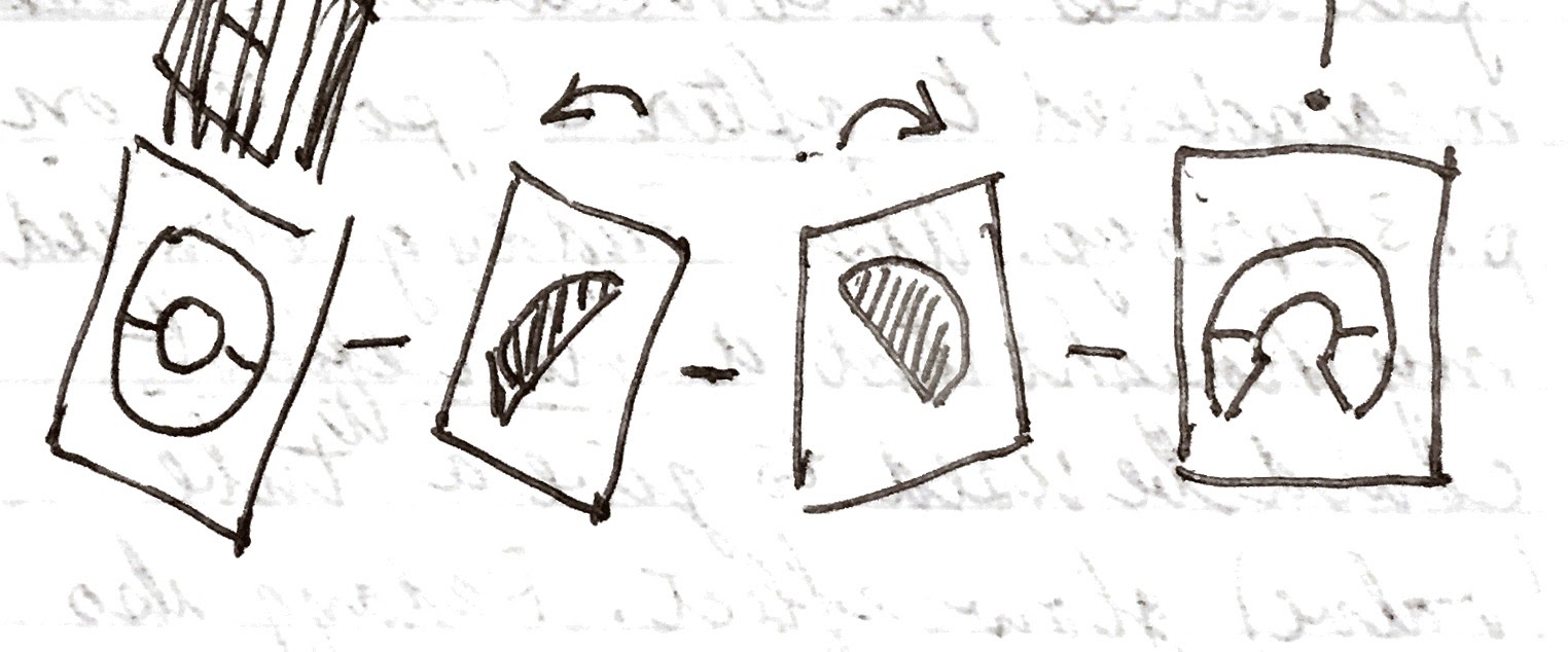
There’s a base drawing of a circle that is half-green (top) and half “blurred” grey (bottom). Two half-circles (“chords”), also green the same shade as the top, are overlaid with pi3d (higher in the Z axis, 1 being higher than 2, etc.) on the base drawing. These rotate in opposite directions from each other, to indicate tuning/signal strength. These will cover more and more of the grey bottom as the signal strength increases, turning the eye more and more green. The chords may expose some of the top parts of the base, so that’s why the top half of the base drawing is green.

Base of Magic Eye


Left and Right “Chords” of Magic Eye Tuner

Tuning into a Favorite
So, I had drawn a radio dial, a Magic Eye tuner and also a dial pointer/needle. How to get all these to work together?
That was a struggle to figure out, but may seem obvious after you read the solution. Read the Egg of Columbus.
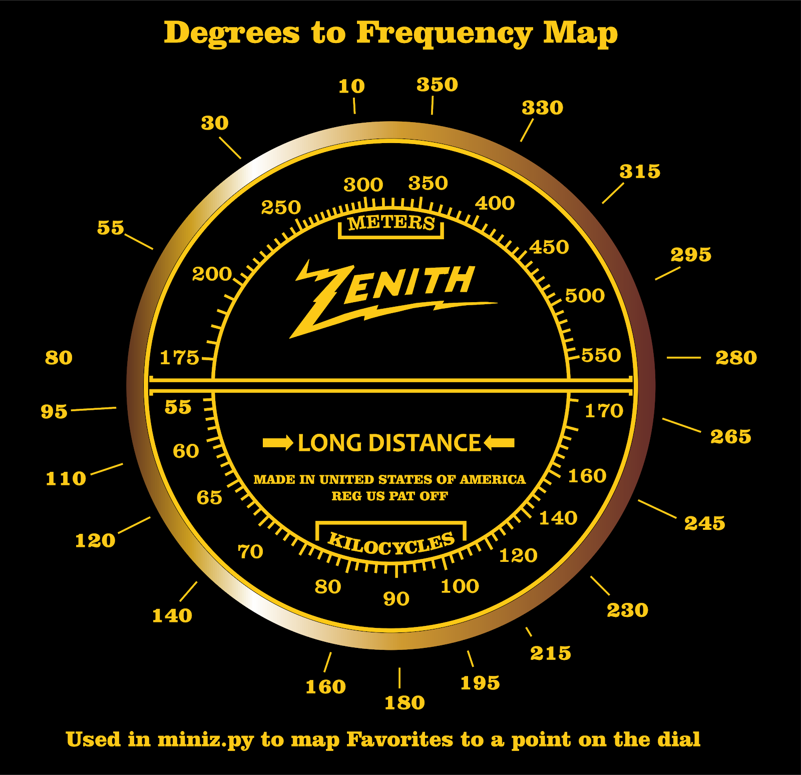
The chords in the Magic Eye turn based on input from a rotary encoder. Frequencies on the image of a radio dial are at fixed locations on a circle. I wrote a quick python script to turn the radio pointer and display the circle degrees of where a given Frequency, say 200M, was located (55 degrees). Then, I could map the circle degrees of that Frequency to a python dict of Favorites (radio/Pandora stations, or playlists). When the rotary encoder turns to a Frequency (say, 55 degrees/200M in our example) that matches a Favorite in a dict lookup, the Favorite plays.
The pointer needle and rotary encoders start at known degrees of a circle by default. This can be 0 degrees or any position you’d like to start at on the dial - doesn't matter. Since Frequency locations are known, and the pi3d python program keeps track of the rotary encoder position, the program can tell if it is approaching or moving away from a known Favorite’s mapped location on the dial. Pi3d can then rotate the chords toward full vertical (no grey showing) to indicate a fully-tuned station, or towards full horizontal (grey bottom fully exposed) for an untuned frequency.
Why the pi Zero W, why not a pi 3? Cost. I wanted to keep costs under $100 USD. A pi 3 would have been $25 USD more.
But, isn’t the pi Zero W under-powered for some graphical applications? Well...maybe. But, not for pi3d software. Pi3d uses OpenGL routines to work its magic. These are run in the pi Zero W’s Videocore 4 GPU, the same chip used in the Raspberry pi 3. Memory split for graphics has to be increased to at least 128MB for pi3d. Programs running under pi3d run quite will under the remaining system memory of 384MB.
I did hit a limit on memory usage, though. I wanted to show weather conditions in addition to a radio dial, clock and Now Playing screen. There was a large image for each of about 10 weather conditions, in addition to all the other images the program was loading. And these images were being swapped in and out frequently. Too much, it just hung after awhile.
Much after the build and hackster post, I built an Art Deco Clock and Weather Display and “may” have solved my memory problem. On the miniz, there were separate drawings which also included a graphic image of the weather condition. For the Art Deco Clock, that changed to a single base drawing, overlaid with a “sprite” (smaller image) of the needed weather condition. Didn’t go back and test it on the miniz, though!
One early attempt was laser-cut plywood loosely based on a Zenith cube radio, only with two speakers instead of one. I mounted a 7 inch Raspberry Pi Touch Screen on it, had a round cut-out for a Zenith radio dial. I even added a cut-out for the “Magic Eye” tuner that would also be emulated on the display screen, in addition to the radio dial.

Early Prototype with Magic Eye Tuner
I wanted to build a good-sized table radio. My wife had other ideas. “You’ve made too many big things that take up too much space. Can’t you build something small?” Design constraint 1 - WAF/PAF (Wife/Partner Acceptance Factor).
About this time, June 2017, I bought the cheap-but-good-enough Monoprice Mini Select 3D printer on a recommendation from my friend John. John and I are like idea curators for each other. Before, with my TechShop San Francisco membership, I made enclosures from acrylics or plywood on a laser cutter, or wood projects with a ShopBot CNC Milling machine. The MP (Monoprice) Select Mini gave me a new platform for Making.
I started off without a plan, just seeing what I could do with the MP Mini Select. I made some small models, very scaled-down so they could print quickly. The goal was to see a thing in my hand, so I could get a better sense of it. I do a lot of concept sketches on paper napkins to start me off. But, you don’t fully understand a thing until you hold it, see it’s use of space.
I modeled in Fusion 360, which had a steeper learning curve than the simple 1-2-3-D I had dabbled in. Fusion 360 is feature-rich and modal: the function/context menu you are in dictates how gestures/mouse clicks work. The gestures/mouse clicks may work one way in a given function, then another way in a different function. It’s kind of a memory workout.To learn it, you have to use it. So, I read tutorials and watched a lot of youtube videos. I imitated what was presented, and tried other things I thought I might need, many times. Many, many times. Until I felt comfortable with Fusion 360.
The first object I modeled was a radio tuning knob. It came out OK, so that gave me some confidence that what I was going to attempt could work.
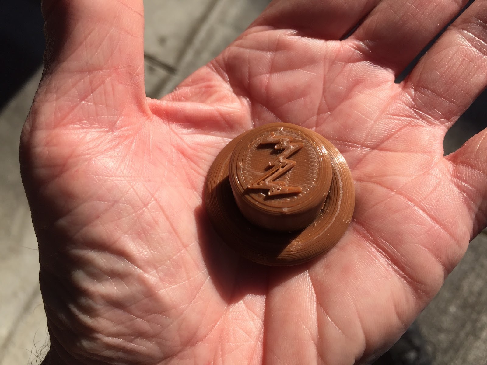
First Print! Zenith Radio Knob
I researched quite a few old radios. Many, like "Cathedral" radios, were very cool looking, but could be hard to print and assemble when scaled up and couldn’t easily fit in all the components: speaker, piTFT display, raspberry pi.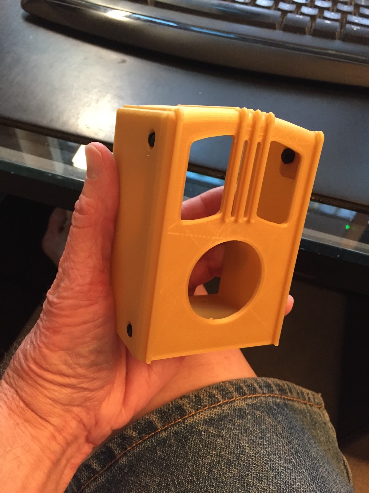
Test Print of a “Walton’s” Style Radio
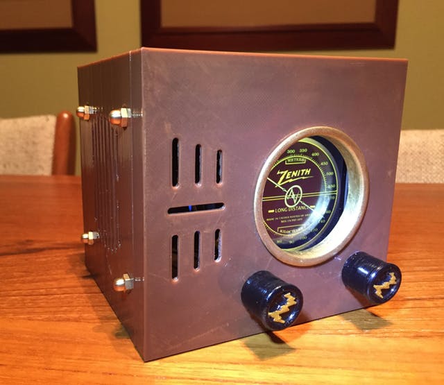
Finally, I settled on the classic Zenith "Cube" 5R216 model. I wasn't trying to faithfully replicate the 5R216. I just wanted something that would suggest the look and feel of it.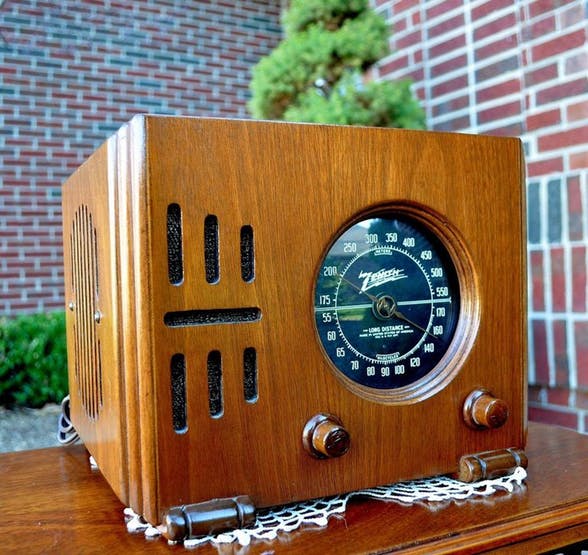 Zenith 5R216 Cube
Plus - the Cube shape would be straightforward to design and print. Or, so I thought.
Alas, after all that work, the Magic Eye was a casualty. There wasn’t enough room for the Magic Eye Tuner - wire routing for the rotary encoders took up space over the bottom of the piTFT display. However, developing the Magic Eye helped me understand the capabilities of pi3d - so it was a good thing!
Skill Level
Advanced - 3D printing, soldering, code installs.
There's a significant amount of soldering to this project, some a little challenging. The real work begins when assembling the components into the 3D printed case. The case is less than 5 inches/120mm square (if you don't scale the 3D print up). If you have large hands you may have a struggle. If you have a larger build-platform 3D printer, I strongly recommend you scale up the box and face - but you'll have to keep the other dimensions the same.
Cost
Around $100 USDHardware components

- Adafruit rotary encoder, On/Off/Volume and Screen Selection, ×2
- Adafruit mono i2s amplifier, Gimme some tunes...,, ×1
- GRS 3FR-4 Full Range 3" Speaker Driver 4 Ohm, Surprising bass and sound for such a small speaker, ×1
- BamTack Dark Brown PLA, Cheap 'n Good!, ×1
- 22AWG wire (generic) - various colors, Wire Adafruit Raspberry Pi Bonnet jumper,s ×1
- M2.5 standoffs/nuts/screws - nylon (generic), Mounts for PI TFT and Raspberry PI Zero W, 4 Standoffs for TFT; 2 for Raspberry PI; 4 screws for TFT; 2 nuts for RPi ×6
- Speaker: Steel 4/40 Screws .375 inch long, plus nuts - 4 screws 4 nuts, I used brass "acorn nuts" for that old-time look. I just like 'em! , ×4
- LEFT Angle Micro USB Connector, To get around the tight fit of the mounted RPi; connect to power, ×1
- Adafruit Raspberry Pi Perma-Proto Bonne,t Wire it up and connect to the pi zero W, ×1
 Breadboard (generic) Test components as you finish a build step ×1
- Adafruit Product 1979 - Raspberry Pi Stacking Headers Use with perma-proto pi bonnet ×1
- Adafruit Product 598 - Female Header For easy connection to the installed rotary encoders ×1
- Adafruit piTFT Plus 3.5 inch Display Product 2441 Touchscreen not used, but need a 3.5 inch display ×1
Software apps and online services
- Raspbian Stretch - Debian 9 Yay! Linux!
- pi3d - 3D python graphics library Powers the custom radio-style dial and shows the other screens
- Logitech Media Server - free, see software config This is the local music server
- Squeezelite - free, see software config This is the music client/player
- pyLMS Talks with Logitech Media Server/SqueezeLite to control the user interface
 Soldering iron (generic)
- 3D Printer I used the cheap Monoprice Mini Select, build volume 120mmx120mmx120mm
- Glue Gun or epoxy, or superglue - glue the case together
- Optional: XTC-3D Epoxy/Resin Looks nice - if done correctly!
- Blue Tack Mounting Putty Needed if using custom radio knobs.
- Neodymium Magnet Use for mounting screws with speaker. Usually available at local hardware store, cheaper than Amazon
2 days, not counting 3D print. 3D print done in two main pieces, 6.5 hours and 11.5 hours, along with 2x 1 hour prints.
Acknowledgement
This project would not have been possible without the contributions and support of the Open Source/Maker Community.Overview
When you're finished with this project, you'll have a working internet streaming radio that's powered by the popular Logitech Media Server(LMS). The client for LMS, SqueezeLite, is installed on the same Raspberry Pi, making a complete stand-alone music system. You'll be able to tune in 5 (or many more, with some minor code tweaks) of your favorite Pandora channels, internet radio stations, or playlists, using the tuning knob. You can also use a supplied web page to control the music, or use IOS/Android Apps. The PI TFT display will simulate a radio dial that works with the tuning knob. The tuning knob will also let you select different screens: an art deco clock, or cover art for Now Playing. A tune button press will toggle pause/play, cycle through display screens and restart the SqueezLite player. The other knob will turn the device on and off, and control volume.
If you want to use Pandora, you must have a paid account.
How it Works
The pi3d graphical software draws the radio dial and needle, as well as an art deco clock and Now Playing art. When the tune knob turns the needle, its location (based on degrees of a circle) is looked up in a dictionary. The pylms software is a python wrapper for LMS commands. If a Favorite is in the dictionary at a pre-mapped location, pylms sends a play request to Logitech Media Server (LMS). LMS then sends a request to the SqueezeLite player to play the Favorite.The tuning knob is also a push button. A short press toggles pause/play through pylms. A long press triggers a screen change to the clock or Now Playing art, or back to the radio dial. Pi3d displays the clock. The Now Playing art and track title is passed from LMS to pi3d to draw. Turning the volume knob up/down sends a request through pyLMS. The volume knob has a push button, too. It can trigger a safe shutdown/power-on/reset. See the Operations section below for more details.

Once a Favorite was tuned, how to actually tell SqueezePlay to play it, control the volume and so forth? There is a CLI available for this, and also commands can be sent with HTML and either of those would work. But they both seemed...verbose, cumbersome. I’d use ‘em if I had to.
Some google searches turned up pyLMS. This seemed a bit more elegant. At least, it looked a more “object oriented”. Plus, the mainline of the python script was less cluttered. Whatever! I liked it better.
About pi3d:
If you haven't seen this powerful software in action, check out the intro on YouTube. The miniz project uses only a trivial amount of its capabilities. Pi3d can draw detailed, immersive, moving 3D landscapes. And, because it uses the Raspberry Pi GPU, it even works on the PI zero.
Process
Test the hardware/software modules while building to make sure everything is working properly, Here's the workflow:- Download/configure/test the required software
- Solder the components and test. Back to software. Repeat as needed.
- Print the 3D parts. Post-process to taste
- Test the completed hardware before final assembly into the case
- Assemble hardware in the 3D case
- Finally - great joy listening to radio station K-YOU (W-YOU East of the Mississippi)
Build
Step 1: Raspbian Stretch Lite- Download Debian Stretch Lite
- Install to micro sd card. This is a good set of instructions.
- Two files need to be added to the /boot directory on the new sd image card.
For Linux/Mac:
 sudo touch ssh
 sudo nano wpa_supplicant.conf
And for Windows/Linux/Mac, enter and save the following, changing ssid and psk to your router's ssid and password:
 ctrl_interface=DIR=/var/run/wpa_supplicant GROUP=netdev
 update_config=1
 country=US
 network={
 ssid="Your network SSID"
 psk="Your WPA/WPA2 security key"
 key_mgmt=WPA-PSK
} ssh "192.168.0.xxx" -l pi
Where "192.168.0.xxx" = your pi's IP address (without quotes). The default password is raspberry. Be sure to change it on first login. You should also configure other settings, as gerrelt recommends, via:
sudo raspi-config
- Network Options/Hostname (I named my host miniz)
- Localisation Options
- Advanced Options - Expand Filesystem and Memory Split
- For Memory Split, change the value to 128 (needed for pi3d, later)
 sudo apt-get update
 sudo apt-get upgrade # This step takes a long time!
 sudo apt-get install git-core
git clone http://github.com/thisoldgeek/miniz Step 2: Prepare Initial Hardware
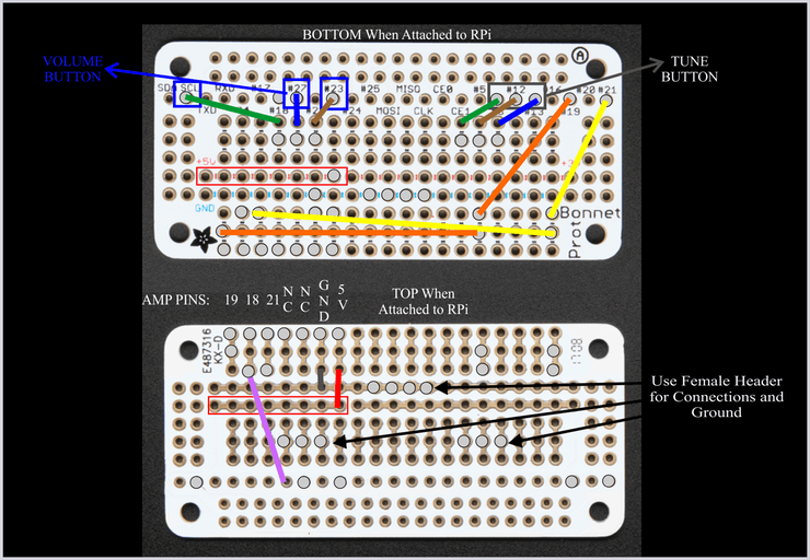
Solder the raspberry pi stacking header to the pi zero. This will connect the mono amp and speakers, via a breadboard, to the pi for sound installation testing. Be careful of orientation. The pi Zero header pins will be inserted into the back of the piTFT. So, all the pins on the pi are upside-down and backwards! This is confusing and can cause errors hooking things up.This diagram should help. Turn the pi so the back of the pi is facing up, with the large silk-screen of the raspberry facing you:
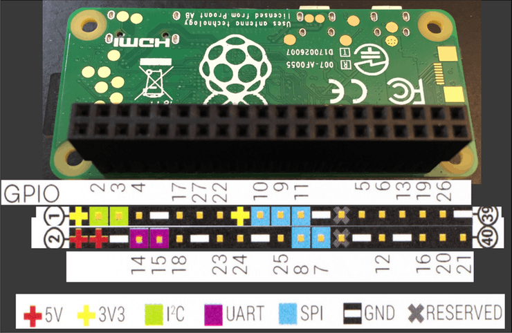
Insert the stacking headers so the female headers are pointed up, facing you. Fasten the headers down with blue painter's tape or blue tack. Make sure they are fully inserted and 90 degrees to the board. Turn the pi over to solder.
Chirality
I have a minor, very specific version of what is called “right-left confusion”. When looking at a circuit board upside-down, I get confused by what is supposed to be left or right (chirality) and mix them up. This also happens to me when watching myself, mirrored, in a video stream like Hangouts. Symmetric placement of parts reduces this, but sometimes there is an asymmetrical arrangement. It’s really easy for me to make a mistake in those circumstances. Compound that by teeny-tiny female headers and bad lighting, and a wire is soldered in the wrong hole.The drawing above mapping out the pin headers was as much a guide for me during the initial construction, as it is for someone trying to reproduce the build.
I found soldering the stacking headers difficult. I had to re-do several bridged solder pins and some that had poor joints. My suggestion is to go slowly and carefully, first soldering the inside pins, then the outside. Work in a single direction, finishing one row of pins at a time.
Next, set up the mono amplifier, a quick soldering job. Adafruit has a complete write-up on the amp at learn.adafruit.com. Follow along in that tutorial and complete all the sections from Overview through Raspberry Pi Test, but Raspberry Pi Setup is essential. To complete the test, you must have your speaker soldered up with two lengths of wire at least 3 inches/80mm long. Heat shrink applied over the joints offers good strain relief. Remember that you have to run the setup script twice!
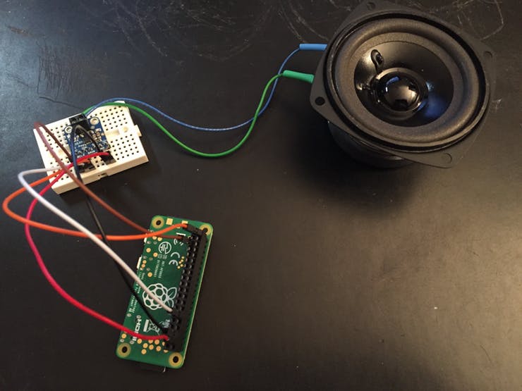
When the mono amp is attached to a breadboard, you may experience some crackling noises. That's because the jumpers may be loose in the breadboard. Try pushing/holding the breadboard wires and you may get cleaner sound. This will be fixed when you have proper solder connections to the bonnet. Also, note that the Adafruit tutorial says to "Solder in both pins with plenty of solder!" on the amp speaker connections.
I chose the GRS 3FR-4 speaker from parts-express because it had mounting holes and good sound frequency range. It mounts directly to the 3D case with screws and nuts, to keep the vintage look. Won't be confused with audiophile quality, but enjoyable to listen to.
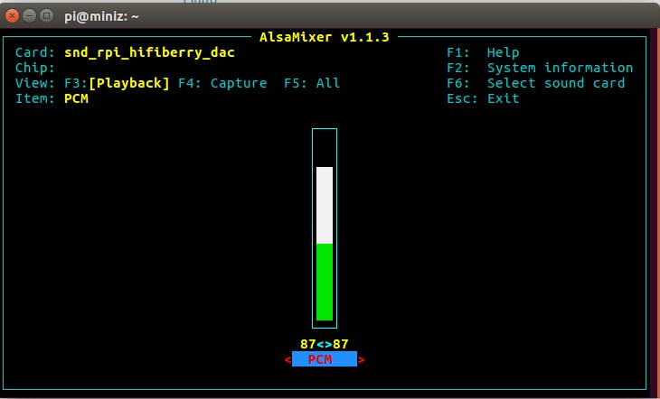
Check the alsa sound controller:
sudo alsamixer
It should look like this:
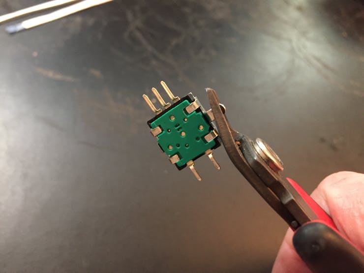
To get the rotary encoders to fit properly into the case, cut the side mounting tabs and carefully bend the solder pins parallel to the base:
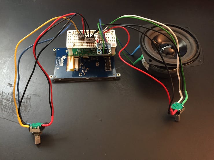
Wire up the rotary encoders, using 2 black wires (GND) and 3 different colored wires for the other pins on each encoder. The different colors will help you tell which encoder connects where, when the encoders are mounted out of sight below the piTFT. Cut the wires about 7 inches/18 cm long. Tin both the pins and the wires with a good amount of solder. For each wire, press the wire into the pin with your soldering iron until solder flows. Remove the iron and continue holding down the wire with your other hand until solder cools. Helping Hands are your friends.
I used heat shrink for strain relief. Gently bend the wires up at a 90 degree angle away from the encoder shaft to fit into the case. Keep your thumb on the pins to prevent the pins from breaking while you make the bend.
Be careful handling the encoder wires after bending! I broke a pin off from rough handling and had to re-do an encoder.
I used different colored wires between the two encoders for the final build. This helped me know when I was hooking up the left-front rotary encoder vs. the right front one, when the piTFT is installed over the encoders and you can’t see what part you’re working on. See ‘Chirality” above.
Your finished encoders should look something like this:
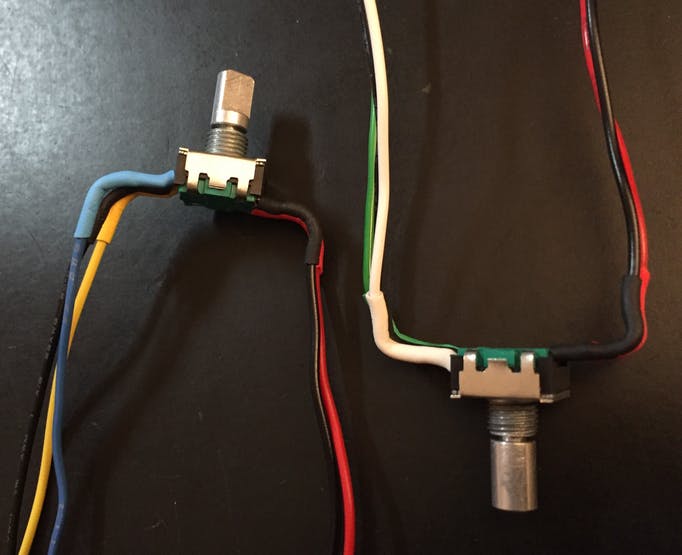
The bend was just a kluge i came up with for fitting the encoders in the confined space. Maybe there’s a more elegant solution to this. I think soldering the encoders to a piece of cut-down perf board would be more robust. But, this worked.
There's a test program included in the miniz directory, test_rotary_switches.py. Connect the encoders to the pi female headers according to the pinouts in that program (TUNE and VOLUME).
To test:
 cd ~/miniz
 python3 test_rotary_switches.py
Step 3: Setup Music Software
The original source for the following scripts is poster gerrelt. Gerrelt has written excellent posts on installing Logitech Media Server (LMS) and Squeezlite.Gerrelt said Spotify was a possibility on this setup. Alas, Spotify support for LMS ceased on July 19, 2017.
Use the scripts in the /home/pi/miniz/scripts directory (created by the git clone) for LMS and SqueezeLite installs (run these one by one):
cd ~/miniz/scripts
 chmod +x *.sh
 ./LMS_install.sh
 ./squeeze_install.sh
The miniz uses a different sound device from the gerrelts tutorial. The Adafruit install software will set up the mono amplifier as an audio source, specifically dtoverlay=hifiberry-dac in the /boot/config.txt. The default hifiberry-dac works without the changes gerrelt needed. HOWEVER: You need to comment out a line in one of the gerrelts scripts to get squeezelite to run. Also, UNcomment the line for SB Server as shown below. Make these changes for the LMS/SqueezeLite to run properly:
 sudo nano /usr/local/bin/squeezelite_settings.sh
 ##but make sure this line is COMMENTED out like so:
 #SL_SOUNDCARD="sysdefault:CARD=ALSA"
 # Be sure to UNcomment this line and add your pi IP address, keep the quotes!
 SB_SERVER_IP="192.168.0.xxx"
 #Then restart the service with:
sudo systemctl restart squeezelite cd /
sudo mkdir music cd /music
sudo mkdir playlists cd /music
sudo mkdir /music/NAS
sudo chmod 777 /music/NAS
sudo mount -t cifs //192.168.0.xx/music /music/NAS -o user=username,pass=userpassword sudo nano /etc/fstab
# add the line below at end of fstab
//192.168.0.xx/music /media/windowsshare cifs guest,uid=1000,iocharset=utf8 0 0Step 4: Configure Logitech Media Server
LMS serves an html page for configuration and control. Connect to it from your favorite browser. Use the IP address of your raspberry pi, followed by :9000, eg. - http://192.168.0.xxx:9000On first run, LMS will prompt for a mysqueezebox.com email and password. Apps like Pandora, TuneInRadio (free streaming radio stations), SOMA and Podcasts require you to create an account on mysqueezebox.com. More on that later. For now, click "skip" at the bottom of the page.
On the next page, navigate to /music (directory created above) and press "Next". Choose a folder for playlists - we created playlists. Click "Next" and then "Finish".
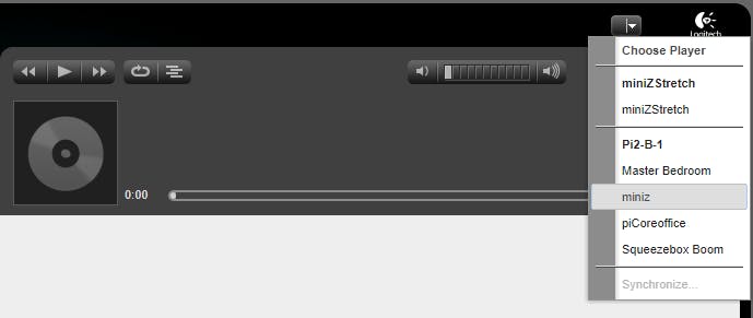
Choose a player from the pull-down in the upper right corner. It's the hostname of your new pi. This should show up automatically if it is your only Squeeze player.
On the left pane, navigate to My Music/Music folder, and hover your mouse over a song or album you want to play. Still in the left pane, but on the right side, three icons will appear. Click on the Play icon to start.
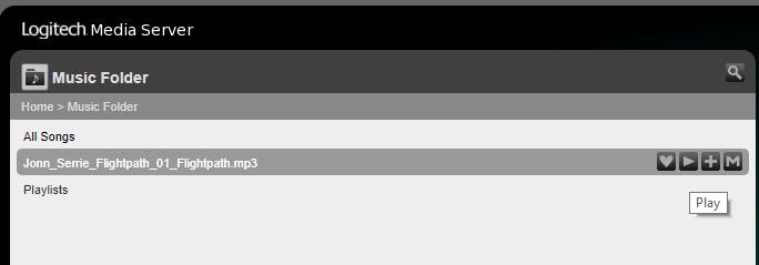
Hey, look at you! You're playing music.
Step 5: Apps
mysqueezebox.comIf you'd like to use Pandora or the other Apps I mentioned earlier, you need to sign into mysqueezebox.com and click on "Create an Account". Save your account information - you need to enter it into LMS after your apps are set up. Once you create an account and login, click on "App Gallery" at the top of the page. Pick an app from the list and click the blue "Install App" button at the top right. After that, click Configure.
- For Pandora, enter the username and password you use for Pandora.
- Click on Player Settings. Your player name should appear in the list.
- Set Status to Enabled and set Home to "Display on home menu".
- Don't forget to click on the blue "Save Changes" button at the bottom of the screen.
Almost done! Click on Settings again, then the tab for Plugins. Scroll down and make sure there is a check mark next to the Pandora app (or whatever app you set up). Click Apply. As an added check, in the "Author" column for Pandora to the right, there should be a link to Logitech. If you click on that, and you are properly set up, the link will open mysqueezebox.com again in the configuration dialog for Pandora. You can close that and click on Close for the plugin page.
Go back to the LMS Home Page; click on My Apps. You should see Pandora, or other newly-added apps under My Apps. If you don't see it, try refreshing the web page. If that doesn't work, try restarting the logitech media service:
sudo systemctl restart logitechmediaserver Setting up Favorites
The radio dial will automatically start playing Favorites if they are linked in a favs dictionary in the miniz.py program.# format below is degrees:fav_number
# see separate guide to LMS for setting up favorites in https://github.com/thisoldgeek/miniz
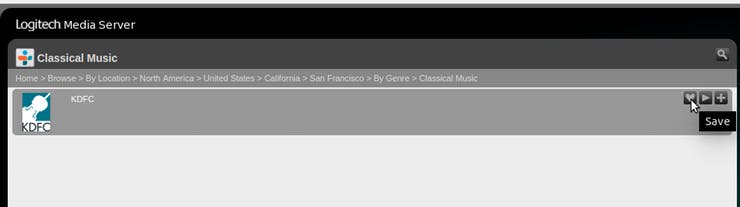
favs = {82:0,57:1,30:2,8:3,352:4,333:5} Here's an example for TuneIn Radio Favorites. The TuneIn App in LMS will guide you to selecting a radio station by several criteria. This example uses:
Home > Browse > By Location > North America > United States > California > San Francisco > By Genre > Classical Music
To create the Favorite, hover your mouse over the heart icon at the right side of the left pane, and click it to save as a Favorite.
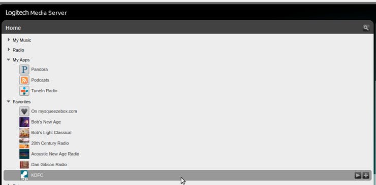
Go back to the LMS Home page (you can just click on "Home" seen in the image above). You should see the new item added at the end of your list of Favorites.
Note: A Favorite for "on mysqueezebox.com" is always added in this list. The list is zero-indexed based. So, the new Favorite created here is number 6.
Step 6: piTFT
Setup the 3.5 inch piTFT for OpenGL using the Adafruit tutorial. Although this is written for Raspbian Jessie, it works for Stretch. cd
curl -O https://raw.githubusercontent.com/adafruit/Raspberry-Pi-Installer-Scripts/master/pitft-fbcp.sh
sudo bash pitft-fbcp.sh 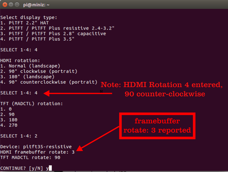
Do the piTFT 3.5inch setup using the manual config operation, with HDMI Rotation option 4 and TFT rotation 2, 90 degrees. This will orient the pi zero, when attached to the piTFT, so its power connector is at the lower right.
To suppress text messages on the screen before the miniz service starts, do:
sudo nano /boot/cmdline.txt
And add:
quiet splash loglevel=0 logo.nologo
To the end of the existing text. Also change:
console=tty1
To:
console=tty3
Step 6: Setup Python Libraries
Run this to setup all the libraries: cd ~/miniz/scripts
./py_libs_install.sh #!/bin/sh
# run installs with sudo!
sudo apt-get update
sudo apt-get upgrade
cp .distutils.cfg /home/pi/.distutils.cfg
sudo apt-get install python3-pip
sudo pip3 install pi3d
sudo apt-get install python3-pil
sudo apt-get install python3-setuptools
sudo pip3 install pylms
sudo cp player.py /usr/local/lib/python3.5/dist-packages/pylms/player.py
sudo apt-get install python3-numpy
sudo pip3 install RPi.GPIO sudo cp player.py /usr/local/lib/python3.5/dist-packages/pylms/player.py cd ~/miniz/scripts
sudo ./pishutdown.sh cd ~/miniz/scripts
sudo ./zdial.sh
sudo systemctl restart zdial Step 7: Preparing the Case
My 3D printer is the small/slow/cheap Monoprice Mini Select. I split the body of the case into two parts - face and case - due to the long print times involved. Here are Cura simulations of the face/case prints and also optional custom knob (2 required).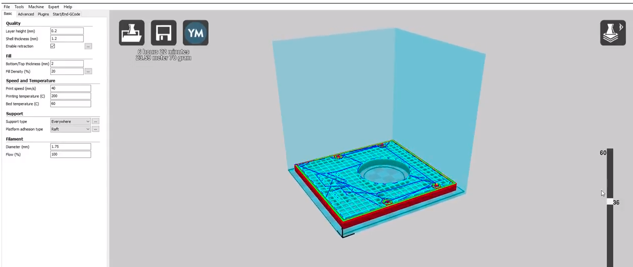
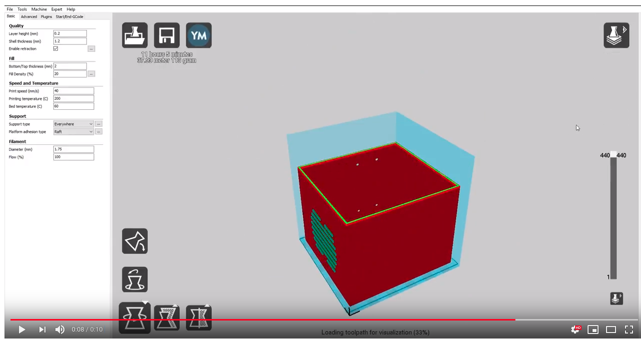

The blue areas are support structures, necessary for speaker grille holes.
There are Cura print settings included in the miniz/docs directory, as well as the STL files.
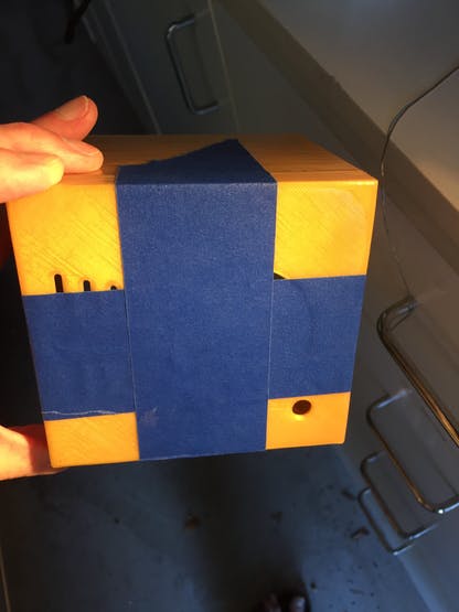
Finishing the case:
- Remove the support material
- Sand the edges to be attached for face and case
- Use blue painter's tape to hold them together
- Glue in 4x M2.5 standoffs in the mounts provided on the inside of the face. Apply superglue to the threads and the bottom of the standoffs, sparingly. Be careful you don't get superglue into the standoff, will plug it. A little masking tape over the standoff screw hole can help.
- Hot glue the inside - use a steady bead of glue for a neater seam
- Option: Finish with XTC3D
- Option: Print custom Z-logo knobs and bezel

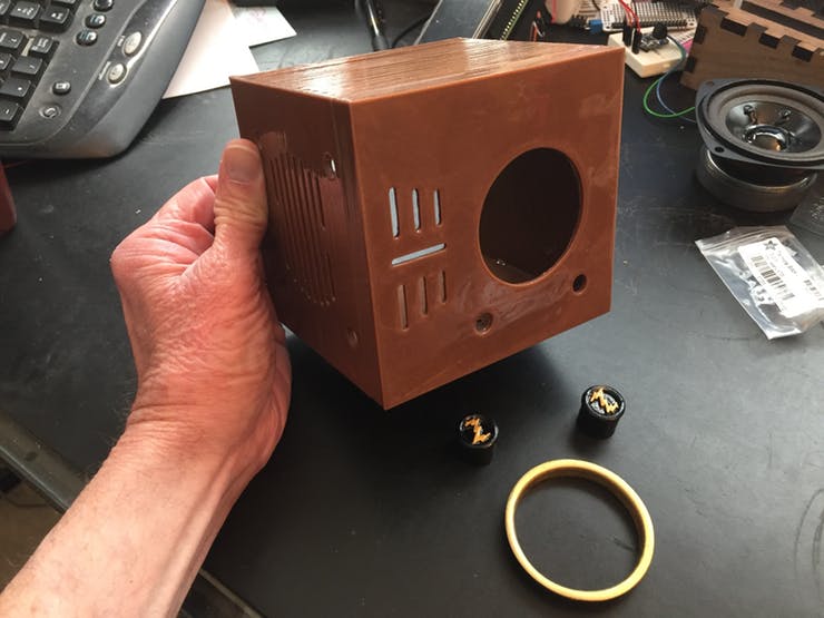
Gluing the face to the case:
The case is ready to assemble at this point. I did a little extra, coating the case with one application of XTC3D, and two coats for the face. This is a good product, and the results can be nice - but there are issues:
- Clean your model with dishwashing liquid and make sure it is absolutely dry
- Use in a very well-ventilated area; has an odd odor
- Use nitrile gloves, eye protection and protective clothing like long sleeves
- Working time about 10 minutes
- XTC3D is somewhat self-leveling, but that means it can flow in places you didn't expect - try to keep your coated model horizontal, or vertical over a catch tray, and watch your hand movements!
- XTC3D can flow to edges and curved surfaces. During the working time, I used a toothpick to keep the XTC3D from building up in rounded grille edges
- The results were nice - shiny and smooth. But there were some tiny bubbles and dust inclusions
- Curing time is usually 2 hours. I touched the model when I thought it was cured and left a fingerprint in the case.
Step 8: Final Soldering
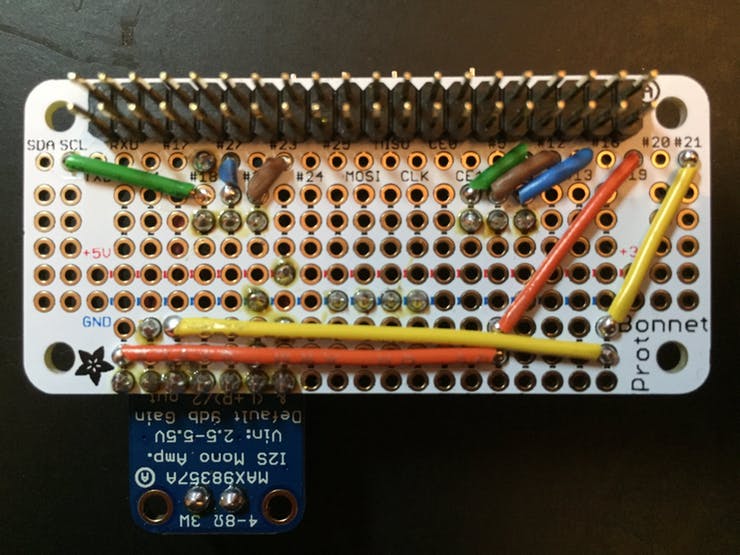
Adafruit has produced another great perma-proto board in the bonnet. However, due to the layout of the raspberry pi, pins may be in an awkward location for your particular application/use. Connecting the mono amp, for example, requires pin 18 on one end of the board and pins 19 and 21 on the other. Some thoughtful routing is required!There's a pin mapping document in miniz/docs for reference.
Split female header into (2) 3-pin pieces and (1) 4-pin piece. There are tips on how to do this on the Adafruit product page.
Solder the wires in this order:
- Double 20 pin male header, short end soldered on "TOP" in diagram
- Female Headers inserted on "TOP" side from diagram
- GND/5V jumpers on "TOP"; the jumpers for #19 and #21 will cover the solder joints for these
- "BOTTOM" wires
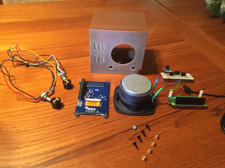
At this point, it's a good idea to do a final check on the hardware components, before stuffing everything into that tiny case.
- Mount the pi to the piTFT display
- Plug the bonnet into the pi
- Insert the rotary encoder wires into the female headers
- Screw the speaker wires into the mono amp
Power UP!
If everything is rosy, you should see this, after about 2 minutes to allow for things to start up:

Okay, you've had your fun. Now take everything apart again so you can put it in the case.
Step 9: Install into the Case
- Install rotary encoders first - turn them about a 45 degree angle to the case to allow clearance for the wires around the piTFT
- Route/organize the wires so they won't block mounting the piTFT or the speaker. The tune knob wires will run underneath the piTFT and the speaker
- The Adafruit encoder knobs work fine. The custom knobs need a tiny bit of blue tack in the shaft to give enough travel to the push button. Works.
- Screw the piTFT into the mounts with M2.5 screws
- Insert steel 4/40 screws into the speaker holes, screw heads on inside of case. I used small (12mm D) Neodymium magnets to hold the lower screws in place until I could mount a nut on the outside. To remove the magnet, hold a finger firmly on it and slide around the speaker frame until free.
- From the outside of the case, tighten 4 brass 4/40 acorn nuts to the screws
- Attach the LEFT angle USB Micro cable to the pi. No space to connect this power cable after the pi is installed
- Mount the pi to the piTFT. Strong light is helpful. Tilt the pi slightly away from the case wall, enough to see the alignment on pins. Make sure the pins are aligned properly and press down slowly.
- Mount the bonnet on the pi, same technique as the pi to the piTFT
- Screw in the speaker wires to the amp
- Insert the encoder wires to their pins and ground
Operations
- Play/pause: hold down tune knob for slow count of 1-2, but first move the needle away from a Favorite. Otherwise, auto-play will keep overriding pause
- Toggle screens: press tune knob down for slow count of 1-2-3-4-5. Will cycle from dial, to clock, to Now Playing and back to dial again
- Restart SqueezeLite: press tune knob down for over a count of 10. SqueezeLite produces distorted audio after 6-8 hours of play, reboots fairly quickly. I leave mine on all the time and fix the audio this way....
- Volume: Up/Clockwise; Down/Counter(Anti-) Clockwise
- Power: Volume button press > 3 secs triggers safe shutdown. When off, shorter (3 secs) press turns pi on. When ON, 3 secs press does a REBOOT
- Now Playing Art: Pandora supplies this automatically. For local music, copy an album cover image named folder.jpg or cover.jpg into the album directory, followed by a rescan (Settings/Basic Settings/Look for new and changed media files). If a local album is missing art, a default image will display.
Quibbles
- The screen, viewed straight on, is colorful and detailed enough. But the display doesn't have a wide viewing angle, so can look washed out from other angles
- Now Playing presents rectangular cover art in a round porthole. Square peg, meet round hole...
- Without the bezel, you can see the edges of the screen
- Shutting down the pi does not kill power to the display - the screen will be dark but you can see light bleed around the edges as seen from the back of the case
- The PWM pin (#18) for piTFT backlight control is used by the mono amp
Added piTFT to Things/Parts List. Thanks for the catch, ChromeBlue!
UPDATE 2018/07/28:
Recommended that you assign a static IP address instead of letting your router assign a DHCP address. The IP address is hard-coded in two scripts:
- miniz.py - executed by the service zdial
- SB_SERVER_IP in /usr/local/bin/squeezelite_settings.sh
Debugging:
If you get a blank display:
 sudo systemctl stop zdial
 cd ~/miniz
 ./miniz.py
Will take awhile to start up. Check for errors that may appear.
UPDATE 2018/07/29:
Fellow hackster Danny Martin sent pictures of his own miniz build. Looks great!Thanks, Danny!

Comments
Post a Comment