2.4GHz (WiFi) Arduino Spectrum Analyzer - Part 1, Getting Started
Parts List:
Arduino seeedstudio clone
OR
Parts for a minimal arduino:
- A breadboard
- 22 AWG wire
- 7805 Voltage regulator
- 2 LEDs
- 2 220 Ohm resistors
- 1 10k Ohm resistor
- 2 10 uF capacitors
- 16 MHz clock crystal
- 2 22 pF capacitors
- small momentary normally open ("off") button, i.e. Omron type B3F
- FTDI USB connector (for programming the Atmega micro)
- 74HC4050 TTL Level Shifter
- CYWM6935 Wireless Module (Mouser)
- SchmartBoard Female to Male Jumpers
Minimal Arduino
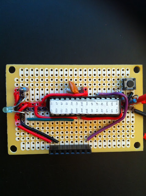
If you'd like to get this working on a breadboard as a prototype, there's a good introduction to a minimal Arduino platform in an ITP Tutorial. One drawback of this approach is the need for some kind of programmer for the Atmega168/328 microcontroller, a tool to get code into the micro. This would be a one-time purchase that's reusable for other projects, but depending on your tool choice, would be around $20 USD. I mention the Arduino Breadboard because the ITP Tutorial has a good description of the layout of parts for a minimal Arduino. It's what I used as a basis for the layout of my own hand-soldered board. I then just added two other critical components, the graphical LCD and the Cypress Semiconductor CYWM6935 Wireless Radio Module, tied to the appropriate pins on the Atmega chip.
One advantage of the breadboard approach is that it's reusable for other projects. Also, unlike the approach shown below, you can swap in/out the Atmega chip in the circuit. That way, you could take another Atmega chip, load it up with a program on the breadboard, pop the newly-programmed chip out and put it into a separate, more permanent purpose-built circuit.
Getting to 3.3V
Electronic parts expect one of two different voltages to represent a digital 1 (on, or high): either 3.3v or 5V; digital 0 (off, or low) is represented by a voltage at or near zero. For this project, the LCD and CYWM6935 expect 3.3V logic as input but the board will be running at 5V, so we have to adjust the 5V down somehow. For this task, one integrated circuit you can use is a 74HC4050 Hex High-to-low level shifter ( I used an NTE4050B, available at my local Fry's). There are other approaches to this problem, but this is conceptually very simple: high voltage logic in one side, low voltage logic out the other.
For a digital logic signal from the 3.3V components, the Atmega168/328 is tolerant of 3.3V as a digital 1, so no special handling needed there.
At this point, you're looking at $10-15 for component parts; $5-8 for a breadboard; and maybe $20 for a programmer. And that's before you get to the key components, the LCD and CYWM6935, which are about $10 each.
Seeedstudio to the Rescue
Another option to drive the prototype is to use a seeedstudio Arduino clone, available for about $22.50 before S/H. The "seeeduino" clone has a switch to adjust the logic output to 3.3V or 5V and has worked fine for my prototyping. Expect about 14 business days after shipping to reach the U.S. A bonus for the seeeduino is that, in addition to female headers connected to the digital pins of the Atmega chip, as on the Arduino, there are through-hole solder points for each of the pins. That's useful in this project, because the LCD and CYWM6935 share some of the same connections, so you could have one component wired to the female headers and the other soldered to the through-holes. Or, solder additional female headers on the through-holes. You could build the entire project on the seeeduino, save some costs, and the basic parts costs would be about $45, including the LCD and CYWM6935.


Comments
Post a Comment