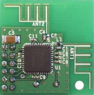
2.4GHz (WiFi) Arduino Spectrum Analyzer - Part 3, CYWM6935 Wireless Radio Module

CYWM6935 Wireless Module
This module is the heart of the Spectrum Analyzer. Since I "borrowed" the code from Richi's Blog, I can't really explain how the code is working. But, it does work! Richi's code examples are available on github.
I fork from Richi's "Fritzing" picture example in my final prototype (no wiring picture available for that, see video below) in that I don't make any attempt at level shifting, I run my Atmega chip at 3.3V directly from a battery.
The tricky thing with the CYWM6935 is the spacing on the already-soldered pins - they're too narrow for standard 0.1" female jumpers that you may get from sparkfun or Pololu. For prototyping, I used some very narrow female-to-male jumpers from SchmartBoard, these worked great. In the finished product, I used narrow-spaced IDC 10-pin female header cable, similar to this one at sparkfun, to connect up the CYM6935.
IDC 2x5 Pin Female Cable
Here's a video showing the transition from prototype to (more-or-less) finished product:


Comments
Post a Comment